
To build this tool I've used two old CD-ROM writer that lays around in my garage.
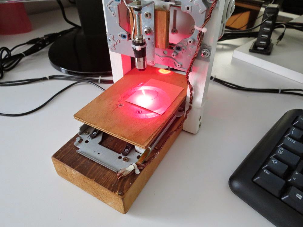
The X/Y positioning system it is build using the CD-ROM motor assembly. For the engraving laser i use the CD-ROM writer laser.
With this hardware the engraving area are will be almost 38mm x 38mm.

I know, there is nothing new in the project i posted here, this is just my implementation of a pretty usefull tool.
The laser used is a red laser diode, taken apart from the DVD-ROM writer optics. It should be 100mA.
In CD-ROM and DVD-ROM you could also find IR driver, DVD laser writer diode will be a little more powerfull than the CD one.
Laser diode usually has three pins, one is the common ground, laser and photodiode cathode (-), one the laser diode anode (+), the other is the monitor photodiode anode(+).
If the diode you are using has no mark, and you do not know the diode pinout, you have to find the laser cathode and anode. One simple method I use is to power up the diode with a 1.8 to 2.2v current, just for a little amount of time, let's say 1s, if it sucks current, that wiring is the laser diode pinout.

Laser diode has to be drive with a proper driver, to run mine, i've used a small and cheap LM358 based adjustable driver, capable of 10mA to 400mA, it also comes with a TTL input pin to enable or disable the laser. You could also use a LM317 to build a simple laser driver, there are many schematics around here, that exaplains how to build one.
A standard 80mm x 80mm pc brushless fan is installed to clear the smoke, this prevents the laser optics lens to be clouded.

The two motors are small stepper, to drive the motors, two EasyDriver stepper driver are used. EasyDriver is a Allegro A3967 based driver board. Motors are powered at 5 volts.
Once again, if you do not know the motors wiring, you have just have to pay attention to pair each coil and then connect to the EasyDriver motor output. If direction is inverted, invert the coil wiring, or just setup grbl to invert the axis direction.

I'm using grbl version grbl v0.8c (ATmega328p, 16mhz, 9600).
You just have to upload the firmware using your favorite uploader, the grbl wiki page drive you on how to do this step.
On the grbl wiki page you could also find any other information about command and software setup.
Commands to the engraving machine are sent through UART.
When you assembly your harware, pay attention to build it making X normal to the Y axis. The two direction has to be perpendicular, or your engraving will has distorsion.
Below you should find the schematics i'm using.

One you have connect and upload the grbl firmware to your microcontroller, you could use terminal software, or a grbl controller to setup your board. I'm using Grbl Controller to setup and send command to grbl, but you can also use a simple terminal.
Below you can find the grbl configuration parameters i changed, basically what i've changed here is:
Set step/mm to setup the correct motor distance to run (a common step/mm value for CD-ROM motor should 53.333):
$0=53.333 (x, step/mm)
$1=53.333 (y, step/mm)
Set the accelleration value to 100:
$8=100.000 (acceleration, mm/sec^2)
Enabled the homing cycle:
$17=1 (homing cycle, bool)
If you need to invert axis direction, "Step port invert mask, int:binary" is the paramenter you have to touch. Those are the most common inversion, but if you need other inversion, look at the grlb wiki for this parameter:
$6=32 (invert x axis)
$6=64 (invert y axis)
$6=96 (invert x and y axis)
To test it, just send the
X10 Y10
command, or use the Grbl Controller rows, you should see a 10mm movement on each axis.
Also check the "spindle on" command power your laser on and off.
Now you could be able to send g-code drawing to your engraver.
There are a lot of software you could use to build g-code draw, the one I use the InkScape.
The working are for this plotter is 38mm x 38mm, so setup your project area to this dimension.
Once you have you path, then you could select the path you want to engrave, and transform it using the InkScape laser engraver extension.
Just copy the extension on your extension inkscape folder, restart inkscape, and use that to build your g-code file.
Once you have your g-code file, you could send it to grbl using Grbl Controller, or other software like Universal-G-Code-Sender.
Notes
- read risk disclaimer
- excuse my bad english
thank you for full sharing your nice projects here, Davide
ReplyDeleteThank you for your feedback! :)
Deletei want this project ardunio code plz send to mail my mail id ijasaslam0@gmail.com
DeleteHello,
Deletethis comment is not an arduino code snatch project. Is run on the same microcontroller of an arduino, the ATmega328, but the code does not contains the arduino framework. Anyway, you can find the code on the grbl page here: https://github.com/grbl/grbl
could i use 3 volts to test the bare diode?
DeleteHello. 3V could do the job, but not more or you could damage the diode. Also limit the current output or you will burn it.
DeleteHI Davide
Deletei have build the same model but i am having big trouble with downloading the grbl controller it gives me an error
(Forbidden 404)
can u maube asist me,,,i like your Build
My email is flip@cmcsa.co.za
thanx
Hello, i use a cheap ebay LM358 based adjustable driver 100mA to 400mA, loaded at 5V.
ReplyDeleteBut i've also try a simple LM317 driver without problems.
Nice project. Please put a fan to blow smoke away of the laser optics or it will deposit burned particles in the lens surface degrading performance. Congrats
ReplyDeleteThank you for suggestion! I'll definitely do it.
DeleteFan installed, look at the new picture above. Thank you.
DeleteHow the mechanism is set to the initial position of the axes? Manually?
ReplyDeleteEnd-point sensors are missing?
Hello, if the grbl homing cycle is enabled ($17=1) the home position is reached every time the engraving begins.
DeleteEnd-point are missing, cause the my cd-rom assembly are end-safe, i mean, the moving mechanism has a spring that prevents the locking of the motor, event if it reach the end of the slide and continue turning.
On a bigger version, or if the motor can break, i should mount end-point sensors, which are supported by grbl.
I do not understand how the controller finds home position without sensors or switches.
DeleteWhen the device turned on, its carriage may be in a unknown random position.
Or grbl save last position in flash?
DeleteIt moves for 38mm every motor, even if the already are at home. It is for this reason important that the motor are end-safe, i.e. they should not break even if the moving attached the the motor is locked because is already at the end of the slide.
DeleteThanks! Now clear!
DeleteNice. Are you sure you are using the laser from a CD-rom writer? They are usually IR-based. DVD-lasers are usually red.
ReplyDeleteThank you for submission. It was a typo error, I've edited the post now, i had write CD-rom writer, but the diode comes from a DVD-rom writer, a led one diode.
DeleteThis comment has been removed by the author.
ReplyDeleteHello, bottom or top part?
DeleteAwesome project. Love the ideas reusing old obsolete hardware.
ReplyDeleteDo you have an example of the LM358 board you used? ebay have a few different options listed.
Thank you!
ReplyDeleteUnfortunately i've no schematics for the LM358 driver. In the picture above, the one of the board, you can see it next to the Arduino core.
Hi,
ReplyDeleteI've bought exactly the same laser driver as you used but I dont know how to connect it. Could you explain what is connected to what? I've got Laser diode -ve and +ve and TTL Control +ve power +ve and power & TTL -ve. What connect to what in the schematics?
Hello, that is the wiring: http://laserpointerforums.com/attachments/f67/29937d1287172551-making-your-aixiz-driver-work-solution-5-aixiz-red-driver-clearer-picture-details.png
DeleteHi,
DeleteI've connected it as on the picture but is it normal that without connecting TTL I have 3,4V on LD+-? When connecting it nothing changes there is alvays voltage on laser output.
I'm sorry but at present, I can not check the levels on my driver. Anyway, to me the laser output shoud not have that voltage when TTL is low.
DeleteThats what I thought. I've connected my driver directly to uart's 3.3V I dont think it can cause this kind of problems but for me laser output is always on even without TTL connected
DeleteThat days i'm full of works and can not test levels on mine, but you could also try a simple LM317 laser driver, i've tryed it and works pretty weel. Remember eyes protection on any test.
DeleteHi,
DeleteI've finally made it work. Is there any good method of setting lasers focus that you would recommend?
Hello, good!
DeleteI just focus pointing to some material, like wood, and trying to get the smallest dot possible. Looking at the dot with safety glasses.
This comment has been removed by a blog administrator.
ReplyDeleteplease give me code program
ReplyDeleteHello, here you can find the code: https://github.com/grbl/grbl
DeleteIt's from the GRBL project.
address email of me ks.phungkiem@gmail.com
ReplyDeleteHi,
ReplyDeleteI've built a laser engraver and I'm using the inkscape with the laser engraver extension. I sent it to the arduino with the UNIVERSAL G-CODE SENDER.
It works, but my problem is that the design is drawn by the laser doing a zig-zag, not keeping the track as the yours do.
Have you any idea for this behaibour?
Thanks
Strange behaivior. May be EMF interference, but it has to be tested. At first, try to move just one motor at time (Machine Control tab on Universa Gcode Sender, not to send a g-code. Check that the motors move the right way, and there are not interfecences between the motor movements.
DeleteI think this is not the trouble. Maybe I've not explained well.
ReplyDeleteThe laser engrever does the design, but doing a line-by-line type plot. For exemple, to make a cercle, it does as the printer instead your video, in which it keeps the track. In this way (as yours) the line is better defined and it takes much less time to engrave
Ok, it seems it's the laser engraver extention for the inkscape the problem. My suggestion is to play around the laser engraver module on inkscape. You could also try some working G-code. This one is a 3,5cm*3,5cm robot that should work: http://pastebin.com/naBuBNn1
DeleteHi Davide Gironi,
ReplyDeleteI build a laser engraver base on your project but I got 1 big problem
I use Arduino mini pro and PL2032 UART
After upload grbl 0.9i to arduino board I try to move axis by axis control tab ( GRBL controller 3.6.1) but it's not work, GRBL just display "error : alarm lock"
I type $X to unlock and move axis again, its just say "error : Undenifined feed rate"
I don't know what wrong with my project ? arduino board/UART board/firmware or GRBL controller software ?
Can you help me fxi that problem ? Thanks so much !
I record this video so you can understand what mean i say because English is not my master language
Deletehttps://www.youtube.com/watch?v=iH8clHtWHHY&feature=youtu.be
Use the grbl unlock command. If you are using GRBL controller it's in the advacned tab, or you can even write it to the terminal input.
DeleteHi friend !
DeleteYou can see I typed "$X" to unlock in my video but it still not work, just display "error : Undenifined feed rate" when I try to move axis after unlock
Everything done !
ReplyDeleteTry downgrade to grbl 0.8 firmware and all work well
I think something wrong with my 0.9 firmware, it only can flash to minipro board by Arduino IDE use source code 0.9, Xloader can't flash 0.9 hex file to mini pro board
Happy to hear this.
DeleteOn another engraveer, I've enconter this issue too using grbl controller on 0.9. You have write the feed rate command by hand. Or, you can use Universal G-Code Sender to resolve this issue.
Sir i want to build one and only the laser diode and driver is left.I bought lm358 ic.Can you send me the circuit of laser driver please.
ReplyDeleteHello, the laser driver circuit used in this circuit was buy on ebay, and I do not have the schematic for that. I've build and check another driver, based on the LM317. You can find the circuit for a LM317 driver searching in google.
DeleteHello, many files are in the link you provided. What exactly should I upload to your AVR? I cordially greet Jacek.
ReplyDeleteThe GRBL firmware. Download the hex from the master branch, or archive here: https://github.com/grbl/grbl
DeleteSelect the version, here i'm using the 0.8c, but the 0.9 also will work.
Now I understand what you are recording a program for avr hex? Do you have to specifically set fusebits Aeacus?
DeleteI do no understand what you mean for "recording a program for".. If you mean, what am i using for upload the Hex to AVR, Then take a look to Extreme Burner AVR, which also can set the fuse for your ATmega328p. If you are using an Arduino board, then the fuse should already be set to the correct values, i.e. set for an external 16Mhz crystal. If it's not so, you have to set fuse to run your ATmega328 at 16Mhz using an ext. crystal.
DeleteThanks for the help. Regards from Polish.
DeleteHi. I think I have a problem in determining the size of the work area Grbl Controller 3.6.1. The program Inkscape workspace is 48x48mm after generating the * .ngc and imported to go Grbl Controller coordinates 330x330mm I even do not know why? Sorry for my english;) I hope you understand what I mean.
DeleteProbably too quickly snatched questions:-) Now I have a problem with setting the machine coordinates because it is too large in terms of 600x600mm course Grbl Controller.
DeleteIn GRBL controller, you should also have the view tab, look here to see if your design is good.
DeleteAlso, this gcode here, should print an airplane. http://pastebin.com/R56Ae3aV
If you are using GRBL 0.9 also set the "x/y max travel".
Already working as it should.
DeleteDo you have a diagram of the laser driver?
Not for this one, this LM358 was buy on ebay. I've built other LM317 using the common schematic you can find in google. They work well.
DeleteThis comment has been removed by the author.
ReplyDeletei can't generate G code in inkscape . It has extension problem , can you provide feedback for me in dilip.maharjan@hotmail.com
ReplyDeleteHello,
Deleteyou could try the InkScape laser engraver extension you can find here: http://www.slackersdelight.com/instructables/laserengraver.zip
This comment has been removed by the author.
ReplyDeleteWhat kind of power supply you use? I saw the pcb with heatsink on main picture, it is kind of voltage regulator I think. – Can you describe?. – How you supply the device via USB or external adapter? Thank you
ReplyDeleteHello, i use a 12V 1A adaptor. The DC DC step down converter converts it to 5V, it's a cheap LM2596 converter, which is used for ATmega board, the laser driver and the motors. The USB it is used only as a TTL adaptor, not for supply purpose.
DeleteThank you very much. By the way you have nice projects on your page, LPM is really cool also. Regards
ReplyDeleteThank you!
DeleteAwesome project, can you share please the ebay link where you bought your lm358 driver, thank you.
ReplyDeleteHello, i can not find the same as i have, this one is next to mine (link expires in 30 days): http://urlgone.com/45c5f1/
DeleteHi. What about the laser itself. What kind of optics did you use?
ReplyDeleteHello. I've used a standard TO-18 laser diode metal housing, it's almost 12mm x 30mm.
Deleteineed to know about the power supply that is not mentioned in the crt!
ReplyDeleteHello, you can take a look at my reply to "chris" September 29, 2015 blog post comment.
Deletei nee to know the power circuit...that is missing in the circuit schematic!
ReplyDeleteHello, you can take a look at my reply to "chris" September 29, 2015 blog post comment.
DeleteHello, it's very nice project, congratulation. I have a question about PB6 and PB7 connection pins, I have bought arduino nano V3.0 (http://img05.deviantart.net/7fdd/i/2014/215/2/a/nanopdf_by_pighixxx-d7thgif.png) and there's no PB6 and PB7 connection, is there any way to connect it? or any other alternative way?
ReplyDeleteThanks for you replay,
best regards, Vidas.
Hello, thanks for your feedback.
DeleteThe Arduino Nano has PB6 and PB7 already connected to the 16Mhz crystal, that's the reason why that connection are not exposed, https://www.arduino.cc/en/uploads/Main/ArduinoNano30Schematic.pdf
Sr i made the laser circuit but i don't what is meant by enable pin from ardunio pin 12
ReplyDeleteHello. The enable pin (the 12, PB4) is the pin to connecto to switch on or off your laser driver.
DeleteGrbl 0.9j ['$' for help]
ReplyDelete$$ (view Grbl settings)
$# (view # parameters)
$G (view parser state)
$I (view build info)
$N (view startup blocks)
$x=value (save Grbl setting)
$Nx=line (save startup block)
$C (check gcode mode)
$X (kill alarm lock)
$H (run homing cycle)
~ (cycle start)
! (feed hold)
? (current status)
ctrl-x (reset Grbl)
ok
ok
$0=10 (step pulse, usec)
$1=25 (step idle delay, msec)
$2=0 (step port invert mask:00000000)
$3=0 (dir port invert mask:00000000)
$4=0 (step enable invert, bool)
$5=0 (limit pins invert, bool)
$6=0 (probe pin invert, bool)
$10=3 (status report mask:00000011)
$11=0.010 (junction deviation, mm)
$12=0.002 (arc tolerance, mm)
$13=0 (report inches, bool)
$20=0 (soft limits, bool)
$21=0 (hard limits, bool)
$22=0 (homing cycle, bool)
$23=0 (homing dir invert mask:00000000)
$24=25.000 (homing feed, mm/min)
$25=500.000 (homing seek, mm/min)
$26=250 (homing debounce, msec)
$27=1.000 (homing pull-off, mm)
$100=250.000 (x, step/mm)
$101=250.000 (y, step/mm)
$102=250.000 (z, step/mm)
$110=500.000 (x max rate, mm/min)
$111=500.000 (y max rate, mm/min)
$112=500.000 (z max rate, mm/min)
$120=10.000 (x accel, mm/sec^2)
$121=10.000 (y accel, mm/sec^2)
$122=10.000 (z accel, mm/sec^2)
$130=200.000 (x max travel, mm)
$131=200.000 (y max travel, mm)
$132=200.000 (z max travel, mm)
ok
ok
I CANT FIND ANY LINES THAT YOU MENTIONED LIKE THESE ONES
$0=53.333 (x, step/mm)
$1=53.333 (y, step/mm)
$8=100.000 (acceleration, mm/sec^2)
$17=1 (homing cycle, bool)
Hello.
DeleteYou have to set lines x and y step/mm according to your motor. Ususally cd-rom motor are 53.333 step/mm.
You can find instruction on how to set those values on the grbl wiki page.
In your case
DeleteType
$100=53.333
$101=53.333
I had to set mine at $0=93.333, $1=93.333.
Deletefor the DVDrom trays i used.
Thank you for sharing this!
Deletei set the values ok then i got a message from grbl controller undefined feed rate ..then i realise that iam using grbl version 0.9 so this version need to specify feedrate i guess.......after all i erase the EEPROM from ardunio UNO and download v0.8 source code instead of grbl master so that is not worked for me...so i again download grbl v0.8 hex file from grbl page and upload to UNO using XL up loader....Now iam totally confused what to do next......sr,please help me i selected this project as my academic project....last date of submission passed yesterday so please help me as much as possible....thnx in advance
ReplyDeleteYou can use both 0.8 or 0.9. But on both version you have to setup the grbl. Check it out here: https://github.com/grbl/grbl/wiki You will find all about setting up a grbl. Basically what i do for this one here it's posted above in description.
Deletesr i setup the hex file into my ardunio uno using xLoaderv after i downloaded the universal gcode sender ...and load the sketch that you provided airplane from paserbin....after i browse the ngc file to g code sender then pressed the send button but i got a message error:Alarm Lock i unlock the code $X after i got the same message in g code sender......please reply fast.... sorry for my doubts sr
ReplyDeleteYou have to unlock the grbl. Take a look here: https://github.com/grbl/grbl/wiki/Interfacing-with-Grbl
DeleteI GOT UNLOCKED MESSAGE FROM GBRL CONTROLLER.MY MACINE IS NOW TURNED ON ALL THE THINGS VERY WELL ON SOFTWARE SIDE ...BUT I HAVE PROBLEMS IN HARDWARE I SEEMS TO WHEN WE BEGIN BUTTON IS SELECTED THE BOTH MOTOR SHAFT IS VIBRATING AND THE SLEDGE IS NOT MOVING BUT THE CONTROLLER IS WORKING GOOD ... I POWERED THE ARDUNIO USING DC ADAPTER 5VOLT 2AMPS I TAKE THE MOTOR SUPPLY FROM ARDUNIO 5VOLT PINS AND GND PIN NOT DIRECTLY FROM ADAPTOR ...I THINK THE VOLTAGE OR CURRENT IS NOT SUFFICIENT FOR MOTOR OR ANY PARAMEETES ERORR IN GRBL .ANY SUGGESTIONS SR... PLEASE REPLY
ReplyDeleteHello, first: do NOT capitalize your message.
DeleteThen, at first try to make motors move on a breadboard? Also connect an amperometer to take a look at current absorbtion.
I got unlocked message from GBRL controller. My machine is now turned on all the things very well on software side ...but I have problems in hardware it seems to when the begin button is selected the both motor shaft is vibrating and the sledge is not moving but the controller is working good ... I powered the Ardunio using dc adapter 5volt 2amps I take the motor supply from Ardunio 5volt pins and GND pin not directly from adaptor... I think the voltage or current is not sufficient for motor or any parameters error in GRBL.
DeleteAny suggestions sir... Please reply.
Hello, thank you for de-capitalizing the message. Have you check how much current the motors draw by using an amperometer?
DeleteHi Davide.
ReplyDeleteJust wondered how you get the laser to turn off when it has to move from one point to another, and then back on again.
My laser is connected to pin 12 of the Arduino and that just switches it on. I get burnt lines when it moves.
Hello, it's the "spindle" on/off command. The G-Code command M3 (enable spindle) and M5 (turn off spindle).
DeleteThanks Davide.
ReplyDeleteI have it working now.
I'm using GRBL 9 and found the fix here:
http://marco-difeo.de/2015/10/13/grbl-0-9j-running-your-laser-with-spindle-pin-on-off
This is the link for the Hex file.
http://pastebin.com/MfWhR9Lk
:)
Well done! And thank you for sharing your solution here.
DeleteNo problem. Thanks again.
ReplyDeleteStuart
Nice tutorial I read, Thanks for sharring Davide :) ask - can I use CNC shield instead EasyDriver Alegro ????
ReplyDeleteYes, it should do the job.
Deleteyour schematic only shows the arduino mini and drivers , hat about the d driver electronics ?
ReplyDeleteHello, I use EasyDriver stepper driver for this project. The EasyDriver schematics can be found online, or any other A3967 compatible board should works.
DeleteHello Davide,
ReplyDeleteI am wondering if your laser engraver may be used also for sponge cutting.
I'm looking for such kind of device but would like to know before starting my project,
kind regards
Hello, I doubt 150mW it's a little too low for sponge cutting, but you may try this just by building up the laser and laser driver. (Note: protect your eyes when you use a laser > 5mW).
Deletemany thanks, I will try soon;)
ReplyDeleteyou sell the machine?
ReplyDeleteHello, no, you have to build it by your own.
DeleteThis is blog is sooo awesome!
ReplyDeleteI went shopping today for components and Nano3 was delivered to the door. I have stripped a DVD burner for diodes and a CD writer for the carriage. I will scrounge for a Diode mount to focus it properly.
I have also downloaded Inkscape with the engraver extn, and checked that it works.
I intend to use the LM317 laser driver with 100R VAR pot to feed the lazer.
I have absolutely NO FKN IDEA how to connect everything but I cannot wait to try. what kind of laser safe glasses do I need for a red DVD laser? there are so many specs and I don't know what the wavelength of my laser is.
I will post back here on progress & issues. Yeeeeeeeeha
Hello, thank you. I'm happy to read this. So at first SAFETY. Rule one: you need a goggles that fits your laser frequency, as example goggles for blue (450nm) does not protect usually for 638nm too (red). Rule two: do not rely on cheap glasses, unless you can test it using a laser meter. The best place you can look at for your glasses is on the laserpointer forum, take a look here for an introduction on safety glasses http://laserpointerforums.com/f53/get-some-safety-goggles-now-75799.html ... it will takes you a quarter, but it may save your eyes ;)
DeleteXLNT! Thank you
DeleteGot Nano3 working on the first GO!
DeletePlugged into USB, Win10 sorted drivers out(I assume)and power LED came on.
I launched XLoader and flashed with:
grbl_v0_9j_atmega328p_16mhz_115200.hex
Got message in bottom left corner to say how many bytes uploaded.
Opened device manager [PORTS com & lpt][USB SERIAL on COM6]
Launched the Arduino 1.6.13 desktop app.
Opened the Blink sketch and uploaded it.
After about 15 seconds of compiling, the PIN 13 led started blinking.
SUCCESS!! first try!
Struggled a bit with Terminal app to run GRBL 9 because I did not realize that the Arduino app actually contains it's own terminal window.
DeleteThen it was a snap. Set the baud rate to 115200 and Carriage Return... and instantly got the GRBL command line cursor:
Grbl 0.9j ['$' for help]
Now going to navigate the settings.
Closed Arduino Terminal and Arduino app and launched the Java based Universal GCode Sender Ver 1.0.9 / Nov 11, 2015
DeleteSet comm port to COM6 and baud rate to 115200, and sent the '$' command and instantly received the help menu.
Opened [Settings/ Firmware Settings/ GRBL] and received the list of settings in a table who's values can be edited by dbl clicking.
So far, so GOOD!
Write my name in InkScape 0.91 and exported gcode file using the GCode extension.
DeleteOpened the file in Universal GCode Sender and sent to Arduino Nano3.
Executed lines of code perfectly.
Now to hook up the EasyDriver 4.4 with a 4-wire bipolar stepper motor.
This is SOOO awesome... I cannot believe how easy this is!
DeleteWell done elektrolyte! :)
Delete@elektrolyte. Just been following your comments. Well done. It is quite rewarding when you take all the time and effort and it actually pays off. I've made 2 now myself but now want to build a bigger cnc machine, just need the money.:) Would like to see yours when you have it just as you want it. If Davide does not mind I can post the links to them for you to look at.
ReplyDeleteHello Stuart, yes of course you can post the link here.
DeleteHi Davide. Thanks very much.
ReplyDeleteThe first one was just to see if I could do it, the second one is a bit smaller and neater/tidier.
They both run on a 16 volt 4 amp laptop power adapter/charger.
I used Arduino UNO's for both with GRBL 0_9j.
https://www.youtube.com/watch?v=CVMAYbJSirA
https://www.youtube.com/watch?v=51bEXfaLiyA
Hello, you've done really a good job! Just a tip and a question. The tip: a fan will prevent your laser lens to get dirt. The question: what's laser's driver circuit you are using?
DeleteHi Davide. Thanks very much.
ReplyDeleteI was going to use a fan but did not have one the correct size at the time. The Laser driver is the one most people seem to use, made with an LM317 Regulator.
I have it on Instructables web site if you want to have a look. I'll just warn you though, it does not look pretty from the back. If you move the mouse over the boxes on the image of the back it will tell you what everything does.
It's here: http://www.instructables.com/id/CNC-Laser-Engraver-1
Thank you for sharing this!
DeleteYour're welcome Davide.
ReplyDeletehow much does it cost to you ?
ReplyDeleteHello, it's made almost on recycled parts, so I suppose something between 10 and 20Euro.
Delete
ReplyDeleteHi could you tell me how the laser did
Hello, sorry i do not understand. How the laser did what?
DeleteDid you any tutorial for how to put the laser of the dvd and how to make his driver.
ReplyDeleteHello, About the laser, there are a lot of youtube video that explans how to extract the diode from a DVD-ROM. About the driver, I've publish my LM317 laser driver circuit here: http://davidegironi.blogspot.it/2015/12/a-diy-a4-laser-engraver-made-from.html but you can also find many video or tutorial on that argument.
DeleteHi, I built same engraver, but with a few modification, one being that I use GRBL v1.1, and the ther being that I control the engraver through laser GRBL, however after attaching everything according to your schematic, my motors run very slowly in contrast to your video, if you have any suggestions, please reply to this or email me at lilhumza@gmail.com
ReplyDeleteHello, did you try to send just a g-code command to move the motor, without using the engraving software i mean? Also you could try mounting the same firmware I have here, if your pinout is the same. It also could be a motor driver issue.
DeleteHello mr. Davide I've done the same laser driver like many tutorials on YouTube but none of them work,,,, what should I do to make it burn?
ReplyDeleteThanks in advance
Hello, it may be your laser driver diode that is burn, also check two times before wiring all the things and take a look to the current absorbtion.
DeleteThis comment has been removed by a blog administrator.
ReplyDeleteThis comment has been removed by the author.
ReplyDeleteThis comment has been removed by a blog administrator.
ReplyDeleteThis comment has been removed by a blog administrator.
ReplyDeleteThis comment has been removed by a blog administrator.
ReplyDeleteThis comment has been removed by a blog administrator.
ReplyDeleteAll the circuit
ReplyDeleteHello, if you mean thatn you want the complete schematics. You can find it in the GRBL wiki here: https://github.com/grbl/grbl/wiki
DeleteHi, maybe you can help me, I'm trying to set step/mm but no matter what value I enter, x & y axis move too far.. (they want to go outside of engraving area). For example, when laser dot is already in the middle of print area (20mm), the preview in laserGRBL shows it's only 3mm or so... I can't regulate it with $100 & $101, if I enter lower values, axis just make more, smaller movements...
ReplyDeleteYou have to calibrate the stepper. There is a small guide here in this post, or a bigger one online. I think the best place to ask this question is the grbl page.
Deletei'm going insane, laser moves 40mm when I enter x steps/mm = 6. Only 6 steps per mm makes x motor run very slow and gets hot very quickly.. I have standard dvd motor and I don't know why you have have over 100 steps/mm... i'm wondering if it's somehow related to microstepping? But when I try to set current limiting via potentiometer on A4988 driver, it has no impact..
ReplyDeleteI would try at first with another driver board, and another motor, just to be sure both the motor and the driver works. Take a look here: https://github.com/gnea/grbl/wiki/Grbl-v1.1-Configuration
DeleteHi! I've done the same project, laser switch on and off correctly but can't cut anything. I have bought a laser pocket, removed the stock diode and i put my dvd laser into this pocket. Have you any advice?
ReplyDeleteThank you very much
Hello. Advice 1: keep your eyes safe using protection googles. Advice 2: it's maybe the lens, laser has to be focued on one small point to cut. Try with a black sheet, it maybe helps.
Deletedear sir.
ReplyDeleteIs this burn copper layer on the pcb???
Hello Rajesh, a ~100mW laser can not do this.
DeleteAwesome stuff.
ReplyDeleteI'm using scavenged CDROM drive stepper motors, and got them moving in x and y axes, but they are running really hot. What values did you use for step pulse time, and maximum rate? Any other ideas on how to make them run cooler? Thanks!
Hello trialex, I've used the default values for all except the values you can find in the blog description above. I can not check the motor temperature of this device now, but if i remeber well, mine too was pretty hot, not really, I can keep hands on it. If they are really too hot you have to check the motor voltage, maybe you are running at an higher voltage.
Delete