
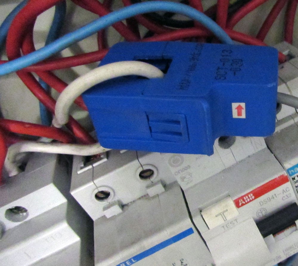
A CT (Current Transformers) sensor is a device used to measure alternating current.
A CT sensor, like other current transformers is made by a primary winding, a magnetic core and a secondary winding. The primary winding is often a single wire passing through the main core of the transformer. The seconday winding is used to sense the AC current passing through the primary winding wire. They are usually build to be clipped on the primary wire. As any other AC transformer the primary winding current produce a change in the magnetic field of the core. This change cause current on the secondary winding.
This library implements a way to read current using a CT sensor on ATmega.
It performs an RMS read on ADC, then computes the RMS voltage on ADC input.
So the primary current Ip is calculated by using the formula
Ip = V * Ns / Rburden
Given
Ns = Turns on secondary coil, i.e. the CT sensor core turns
Rburden = Burden resistor of the CT sensor.

Below some tips on how the CT sensor works, and how to find an appropriate value for the burden resistore.
Given
Vp = Voltage on primary
Vs = Voltage on secondary
Np = Turns on primary
Ns = Turns on secondary
Ip = Current on primary
Is = Current on seconday
CTratio = Np / Ns
From the Faraday's Law
Vs/Vp = Ns/Np
And, due to conservation of energy
Vp*Ip = Vs*Is
So
Vp = (Np/Ns)*Vs
and
Vp = (Vs*Is)/Ip
Then
CTratio*Vs = (Vs*Is)/Ip
Simplified:
Is = Ip * CTratio
Using the ADC of our microcontroller we can read voltages, so we need to "convert" the current output of the CT sensor to voltage. We can doing this using a resistor, the burden resistor.
To calculate the burder resistor value we need a few information.
We need to know the current range of our CT sensor, let's call this Imax.
Then then number of turn on secondary (Ns).
Then the ADC reference voltage, usually 5V on ATmega (AREF)
We have to select a burden resistor that products the voltage we want. In our case, we would like to product a voltage equals to AREF/2
So
Rburden = (AREF/2) / Isp
Given
Isp = Peak current on secondary
Ipp = Peak current on primary
Np = 1
We also know that
Isp*Ns = Ipp*Np
so
Isp = (Ipp*Np) / Ns
Now we can convert RMS Ip to Peak to peak current
Ipp = sqrt(2) * Ip
And
Isp = (sqrt(2) * Ip) / Ns
Simplified:
Rburden = (AREF*Ns) / (2*sqrt(2)*Imax)
Below the schematics used on the ATmega sample.
Notice the two biasing 10k resistors.

Code
Notes
- read risk disclaimer
- excuse my bad english